The next step was brought about by improvements in high power audio frequency (AF) transformer design allowing the final RF stage (in class C, a highly efficient mode) to be transformer-coupled to a high power modulator in push-pull class B . Overall efficiency from mains input to RF at the aerial was raised to over 50% by these advances but more was to follow.
By the 1960s power Tetrode (4 electrode) valves had become available. Tetrodes had long been available in small receiving type valves and transmitting valves capable of a few kilowatts but very high power versions took longer to develop. Tetrodes have much higher amplification than triodes. Whereas a triode amplifier might triple or quadruple the signal power a tetrode could multiply it by ten. Together with the advance of transistors it meant that high power transmitters could be made with few valves, leading to higher efficiency approaching 75% overall. By the 1970s MF (medium wave) transmitters using this technology were capable of 1 MW (one megawatt, a million watts) of carrier power. With special modulation techniques the carrier could be driven upwards to 125% of its unmodulated level. This implies a peak power of approaching 5 MW, a colossal amount of power requiring high quality engineering.
This technology was “borrowed” to feed large amounts of RF power into machines researching
Nuclear Fusion. The JET (Joint European Torus) project near oxford includes several 1 MW RF generators to produce the energy required for fusion to occur.
Perhaps the penultimate stage of development of AM transmitters is the use of “switched mode” modulation, often using solid state devices. Rather than superimpose high power audio onto a fixed high voltage supply by means of a costly and difficult audio transformer, a continuously variable supply capable of varying at an audio frequency rate is provided . Switching devices have high efficiency as they are either “off” using no power or “on” passing a signal with very little loss. So a high voltage is pulsed by such a switch at a frequency much higher than the highest audio frequency. When the resulting pulses are passed through a filter which will not pass the repetition frequency, the voltage is averaged out with no trace of pulses remaining. By varying the width of the pulses the average value changes and so can be varied to reproduce the high voltage supply modulated by the audio signal.This technique allows the production of high power transmitters with overall efficiency around 90% .
The final chapter in the amplitude modulation saga is the use of totally solid state transmitters. Transistors
are relatively small devices. Those designed for use at RF are limited to a power of a few hundred watts.
However, at medium wave and lower frequencies transistors can be used in a high efficiency “switching” mode up to about 1 kW. This is a long way from 1 MW but by combining many such devices transmitters of 100 kW rating have been successfully manufactured. The methods of combining being the result of much ingenuity.
This represents the ultimate in AM and perhaps the peak of high power transmission. Some broadcasts still use this mode but other systems, capable of higher quality or extra facility have tended to overtake the technology. For information on these please move to the next page.
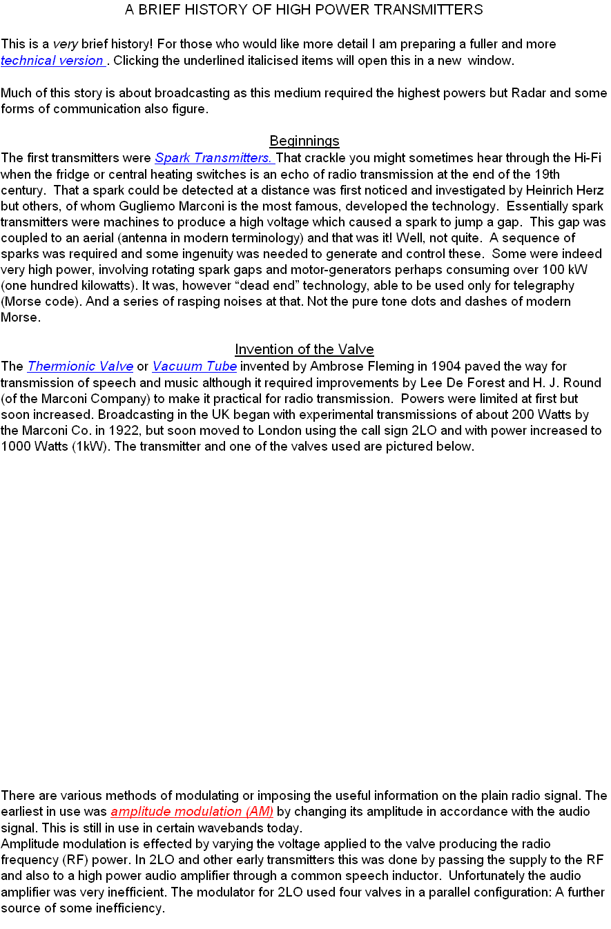
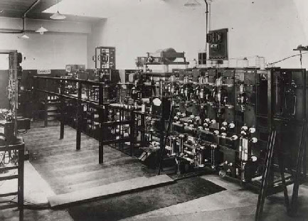
1 kW was about the maximum power which could reasonably be obtained with the early valves which consisted of a structure of metal electrodes contained in a glass housing about the size and shape of a rugby ball. The interior was a vacuum, necessary for the operation of the valve. Thus, waste heat, of which there was a lot, could escape only by radiation or by conduction along the small connecting leads which passed through the glass. The anode (positive electrode) where most of the heat is produced thereby glowed red hot. This problem was compounded by the low efficiency of the circuits used. The major source being the method of modulating the radio signal.
Achieving Higher Power
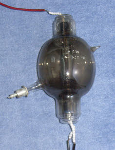
One step forward was to improve the cooling of the valves. This was first done by making the copper anode part of the vacuum envelope. Advances in the technique of sealing glass to metal were necessary as rather than a few smallish copper connections passing through the glass the entire anode needed to be sealed. Having done this, the anode could be cooled by placing it in a container through which water was pumped. The anode is at the highest voltage found in the transmitter but high voltage and water are not good mixers. The solution was to use de-ionised water and long lengths of pipe. Similar construction techniques with the anode provided with fins and placed in a stream of forced air for cooling was possible.
Much later (c1955) water was made to boil on the anode and the heat taken away as steam allowing even higher power valves to be made.
Further advances were made in the efficiency of the transmitter. The early method of modulating using an inductor in the common supply to the modulating valves and the RF valves required the former to be in class A (a mode of biasing and operating the valves) which is not efficient. Improvements were effected by modulating an early low power stage of the RF chain and then amplifying the modulated wave. These amplifiers could be in class B which is more efficient.
Further advances were made in the efficiency of the transmitter. The early method of modulating using an inductor in the common supply to the modulating valves and the RF valves required the former to be in class A (a mode of biasing and operating the valves) which is not efficient. Improvements were effected by modulating an early low power stage of the RF chain and then amplifying the modulated wave. These amplifiers could be in class B which is more efficient.
A water cooled valve