BEGINNINGS
It began with SPARK TRANSMITTERS
Essentially, these were a telegraph key controlling an induction coil with a spark gap coupled to an aerial (antenna in modern terminology) by some means. On a certain dramatic night in April 1912, the Titanic, the Carpathia and the California would all have had such transmitters. Unfortunately that of the California was unmanned at night and the Titanic’s transmissions were not received by this closest ship.
The simplest spark transmitters were formed of an induction coil and spark gap connected to an oscillatory circuit which may have been formed of condensers (capacitors in modern nomenclature) and inductors (coils) or have been just the antenna itself. The primary circuit of the induction coil would include a vibrating contact which opened and closed, making and breaking the circuit like a buzzer. Each break would produce a spark in the secondary circuit.
As powers increased the equipment became quite complex, involving rotary alternators to energise the coil and increasingly ingenious spark gaps. This could be arranged to produce one or two sparks per cycle of the alternating supply. The frequency of the break contact or of the alternator would determine the “note” heard at the receiving station. Thus, frequencies in the 500 Hz region were common rather than the 50 or 60 Hz of our normal mains supply as such a low frequency would be unpleasant to listen to.
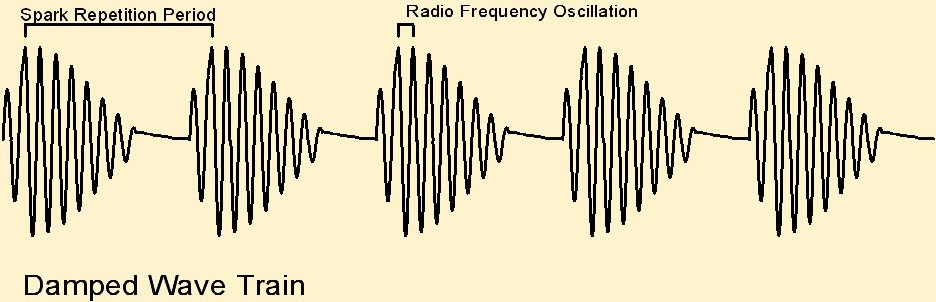
Just to produce a spark was not sufficient. Although the spark contains a lot of radio frequency energy it is spread over many frequencies (wavelengths) and needs to be concentrated. In fact, a regular chain of sparks is necessary. Each spark excites the radio frequency oscillatory circuit and produces a burst of rf energy which fades away as it is radiated or dissipated in the circuit resistance thus producing a damped wave. Such a wave contains frequencies of the spark repetition rate and some related to the rate of decay of the burst in addition to the radio frequency so the received note would be harsh.
A further problem is heating of the metal spark gap and the air surrounding it. This causes the spark to maintain itself and no further energy is converted to rf. Various ways were employed to counter this including blowing air across it and the rotary gap. This latter consisted of a series of electrodes mounted on a wheel (which was sometimes on the shaft of the alternator providing the basic power). As each electrode passed by a fixed electrode it formed a spark gap but was rapidly drawn away, quenching the spark and allowing the electrode to cool. The next electrode then came into proximity allowing another spark to pass.
Transmitters with powers of up to 100kW (one hundred kilowatts) were made in this way although a few hundred watts was more usual and as this referred to the power input to the entire system, precisely what this meant in terms of radio frequency energy is questionable. Large voltages and currents were often involved and operating such equipment would have been a noisy, uncomfortable and rather dangerous occupation.
Below is a typical circuit of a spark transmitter:
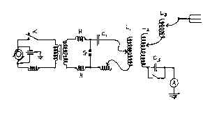
When the signalling key K is closed current from the alternator flows through the primary of the induction coil. As this could provide perhaps 120 Volts ac (at perhaps 500 Hz) at 20 Amps operating this key was no trivial matter. A current is induced in the secondary and charges capacitor C1 until the spark gap G breaks down, triggering rf oscillations in the coils L1 and L2 and capacitor C2 which are radiated by the antenna. The switch which appears to short out C2 was presumably to allow static electricity to bleed from the aerial when not in use.
This type of transmission was limited to telegraphy and thus was a dead end technically. In fact spark transmissions were banned except for emergency use at sea in the 1920s. It required the invention of the thermionic valve or vacuum tube before continuous radio waves capable of being modulated with speech or music could be generated so leading to the introduction of broadcasting and increasing power.
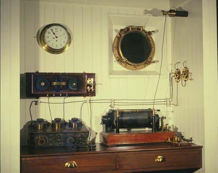
The picture shows a typical small ship installation of the early 1900s. The spark transmitter is on the right with the actual spark gap just visible in front of the induction coil . Stiff connections lead through the bulkhead to the aerial.
The equipment to the left is the receiving apparatus -