Thermionic Valves, or just valves, and known in the USA and elsewhere as Vacuum Tubes, or just tubes, were a development from the early experiments of Thomas Edison to manufacture a satisfactory light bulb. He noticed an effect which was followed up by Ambrose Fleming in London who eventually produced what we now call a diode, a two electrode device. This could be used to convert ac to dc but could not amplify signals. In the early 20th century, the American Lee de Forest inserted a third electrode to form a triode, however it did not become a practical amplifying device until modified by H. J. Round who worked for Marconi.
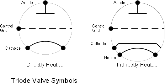
The circuit symbols for triode valves are shown below, although these are not representative of the actual construction.The triode comprises a negative electrode termed the cathode. This must be heated to red heat either directly as in the filament of a light bulb or indirectly with a separate heater enclosed in a tube which is itself the cathode. The Anode or positive electrode is usually a further tube which surrounds this cathode at some distance from it. In between is the Control Grid made of fine wire or mesh.
The triode has limitations due to the interaction between the control grid and the anode. This was later overcome by adding a second grid known as the screen grid between the control grid and anode to form a four electrode device or Tetrode. A fifth, sixth and seventh electrode were also added but generally their use was limited to specific applications and were not found in high power transmitters.
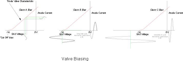
The efficiency of a valve used as an amplifier depends upon the biasing arrangements:
I.e. The precise voltages applied to the control grid. Unfortunately the linearity
of amplification achieved is in inverse sense to efficiency. A Hi-
In Class B the valve is biased in such a way that with no signal applied no current
flows. Only the positive going half cycles of signal are amplified. This is clearly
of no use for distortion free amplification. However, in a radio frequency amplifier,
the presence of a tuned circuit can provide a flywheel effect which re-
For even higher efficiency, class C has the valve biased so that current only flows
for less than half a cycle. The smaller the portion of the cycle during which current
flows, the higher the efficiency. Figures of over 90% can be achieved. It is highly
non-
The following diagrams give some idea of the operation: