While the content is believed to be accurate it is surely not complete. Much more information can be found on the web. In particular www.marconicalling.co.uk is worth a visit.
In order to explain fully the development of transmitters over the years it is unfortunately necessary to use some technical terms. What follows is an attempt to explain those terms as simply as possible:
Firstly; to explain RADIO WAVES. Radio waves (not to be confused with radio activity) consist of electromagnetic waves in space. That is a combination of an oscillating electric field and an oscillating magnetic field of the same frequency. In order to radiate, these must be at right angles to each other in space and shifted in time by one quarter cycle of oscillation. Producing these conditions is the job of the AERIAL or ANTENNA (the modern term) and does not concern this treatise. The Transmitter merely produces an electrical signal of the appropriate power and frequency to supply the antenna.
Power for domestic use is provided at a FREQUENCY of 50Hz (or 60Hz in some countries) ac (alternating current). That is the current rises from zero to a maximum value (following a curve known as a sine wave) then decays to zero and rises to the same value in the opposite sense before falling to zero again and repeating the cycle. It does this 50 times in each second. In fact it was once described as 50 cycles per second (c/s). The description was changed to Hz or Herz in recognition of work by the German physicist Heinrich Hertz in the 19th century. It would be possible to radiate waves of this frequency if only a suitable antenna could be constructed. It would need to be about 1000 miles long! Radio only becomes really practical at about 10kHz (ten kiloHerz or 10,000 Hz) and even then only for special purposes. Some Navigation systems operate at around 100kHz, Broadcasting commences at around 150kHz (Long wave) and continues up via Medium Wave (around 1 MHz, 1 MegaHerz or 1,000,000 Hz) and Short Wave to much higher frequencies. Radar uses frequencies of several GHz (GigaHerz or 1,000,000,000 Hz).
Early radio was usually specified by WAVELENGTH. Frequency and wavelength are related. Radio waves travel at the speed of light (very nearly 100,000 km per second) and it is easily shown that Wavelength in metres is the speed of light in m/s divided by the frequency in Hz but by putting in the multipliers for kHz and km we get:
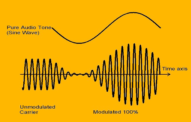
A simple radio wave, often referred to as a CONTINUOUS WAVE or CW can carry no information
other than that it is there. Hence it can be used for sending morse code by breaking
it up into short (dots) and long (dashes) periods of being present. To carry more
complex information such as speech or music it must be MODULATED. There are various
methods of MODULATION, the earliest and perhaps the simplest to understand is AMPLITUDE
MODULATION or AM. Clearly the amplitude is varied by superimposing the modulating
signal upon the plain continuous carrier. At first sight the amplitude may be varied
down to zero and up to twice the carrier amplitude. This is termed 100% modulation.
However, by pre-
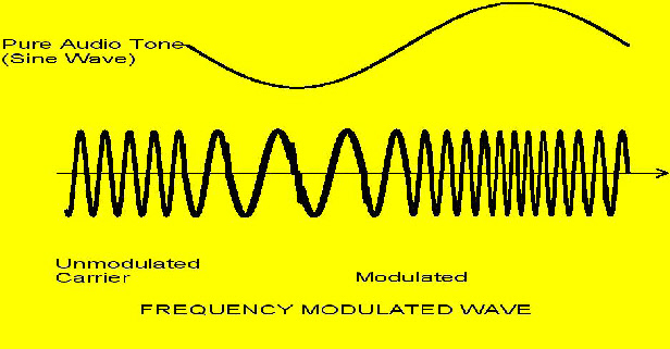
There are other, more complex, forms of modulation of which the most common is FREQUENCY MODULATION or FM. In this system the amplitude of the signal remains constant but the frequency of the wave is varied in sympathy with the modulating signal.
Therefore the wider spectrum of VHF is employed: Band II (the FM band) being about
20 times the available spectrum at medium wave (MF). Because of the differences
in propagation of MF and VHF more transmitters are required at VHF but at lower
power. A typical MF transmitter would be rated at 50kW carrier whereas at VHF 10kW
would suffice. Although generating a stable, high quality FM signal is a technical
challenge (particularly if stereophonic transmission is involved) the remainder of
the transmitter is simple. Since no variation in amplitude occurs all amplifiers
can be in high efficiency (but non-
The diagram is for illustration only as a pure tone would be unusual, produced perhaps by some musical instruments, but most music and speech is complex, consisting of many tones together.
The advantage of FM is that it can be made relatively immune to interference of the sort which affects AM and is capable of higher “fidelity”.
The disadvantage is that to do so requires a much greater bandwidth:
i.e. It takes up a wider part of the available frequency spectrum. Whereas an AM broadcast might occupy 10kHz, a quality FM signal would require 200kHz. Thus it is not used on the medium wave band where there would be only about 5 or 6 such channels.