Other Forms of Broadcasting
By the 1950s amplitude modulation was being overtaken for quality broadcasting by Frequency Modulation. In this case the amplitude of the transmission is constant and the frequency is varied by the modulating signal. The requirements of the power amplifier become much simpler and can use the high efficiency class C. There is no high power modulator. Producing a stable, low distortion frequency modulated signal is in fact quite a task but not part of this story. The signal occupies a much wider bandwidth, about 200 kHz for high quality. Medium wave being unsuitable, as there is room for only five or so channels of that width, FM moved to higher frequencies around 100 MHz. As a result of the way the antenna behaves and the signal is propagated at these frequencies, really high powers are not necessary and powers of 10 or 20 kW are about the maximum, generally using air cooled valves.
Also, television arrived on the scene in the 1930s. Initially, the transmission frequency was quite low , around 45 MHz, and power requirements less than 20 kW. Modified short wave transmitters could be used. However, the television waveform cannot easily be passed through a transformer so high level, high efficiency modulation could not be used. Instead the modulating signal was applied, together with the RF signal, to the grid of the final amplifier. This form of modulation is never highly efficient and the form of the TV waveform makes it less so. However, this remained the usual system as TV spread and occupied higher frequencies up to 215 MHz in band III which was used by commercial TV. Air cooled tetrode valves were the norm and powers up to 50 kW peak white (see below) were achieved. Sound was carried on a separate AM transmitter of lower power.
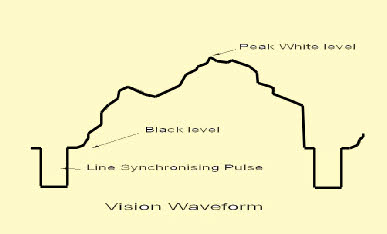
screen but the object was to avoid such interference being mistaken for synchronising pulses which could have occurred if the modulation was inverted.
By 1960 the pioneering 405 line system was ready to be replaced by a higher definition 625 line system to an international standard (although fine details of the transmission vary from country to country). The increased number of lines meant that the transmission occupied greater bandwidth and required a move to even higher frequencies in Band IV and V (up to nearly 900 MHz). The modulation was inverted compared to the earlier system,with the synchronising pulses now setting the peak output. Sound would be transmitted as FM. Eventually colour transmission was to be introduced and all new transmitters were designed with this in view. The transmitted signal became complex; in addition to the monochrome or luminance signal as above and an FM sound signal, there would be a complex colour or chrominance signal. The international discussions as to the precise form of these signals, NTSC in USA, Secam in France and PAL in Germany and eventually in the UK, are a separate story.
Transmitting this new complex signal at the high frequency chosen was (and still is) not easy. Tetrode valves could be made to operate at these frequencies but the technology was stretched to its limit. The power which could be achieved was limited and valve life was a problem. The solution was the Klystron, a microwave amplifying device originally intended for radar application. Although still a type of vacuum tube, insofar as it is a vacuum device with a cathode which emitted electrons as in a gridded valve, the mechanism by which it amplifies is totally different although it later acquired a grid and became a klystrode.
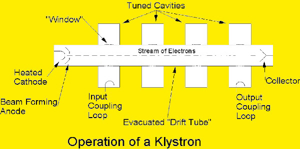
While transiting this space the electrons pass a number of metal cavities which are tuned to resonate
at the frequency of the signal. The cavities are electrically coupled to the electron beam by “windows” of insulating material. A signal injected into the first cavity causes an alternating electric field across the window which affects the velocity of the passing electrons. Alternate half cycles accelerate and slow the electrons. The faster electrons then start to overtake the slower ones causing bunching. As they pass the intermediate cavities, which have no external connection, they set up a field within the cavity which then further increases the bunching. At the final cavity the bunched electrons set up a very strong signal in the cavity and this is extracted as a much amplified replica of the input. Amplification of 100 times is possible.
The disadvantage is that it is not very efficient! The electron beam consumes a great deal of power, perhaps three or four times the maximum output that can be obtained. Since this maximum is only required at the peak of the synchronising pulse, the overall efficiency is quite small.
Complex arrangements to reduce the beam power by varying the voltage applied were attempted but the solution eventually adopted was to introduce a grid between the cathode and the beam forming anode. This allowed the beam power to be varied very easily so it could follow the requirements of the transmitted waveform. This is the Klystrode which gives much higher efficiency and remains supreme for high power UHF TV transmission.
All of these devices still produce a large amount of waste heat. Techniques such as vapour (steam) cooling as developed for earlier am transmitters are still employed.
Alas this form of TV transmission is becoming a thing of the past; replaced by digital methods which require rather lower powers usually produced by solid state devices (transistors).
The sketch is a representation of a monochrome vision
waveform for one line of the picture. In the early days of TV in the UK there would be 405 of these then a more complex frame synchronising pulse. The pulse is there to ensure the receiver begins to scan a new line of picture correctly. In the absence of any picture the waveform would be a line at black level with the synchronising pulses still present. There is no obvious “carrier” level as in normal AM. It was decided that black level should be set at 30% of peak amplitude and a white picture would require peak signal. In some ways this was unfortunate as impulse interference such as from motor vehicles caused white flashes on the
Here is a diagramatic representation of a Klystron. Electrons are emitted by the heated cathode just as in a thermionic valve. They are accelerated towards a positive anode but this is so shaped that they pass through it and enter a long evacuated tube known as a “drift tube”. The beam requires focusing. This is accomplished by fairly massive electromagnetic coils around the tube.