RADAR (Radio Direction Finding and Ranging) is another user of high power transmitters but very different from Broadcast use. Essentially, a very short pulse of radio frequency energy is emitted from a highly directional antenna. If the pulse finds a target some energy is reflected and can be detected by a receiver. As radio waves travel at a fixed speed, the time interval between sending the pulse and receiving the reflection gives the range to the target. The direction is revealed by the pointing of the antenna. Only a tiny fraction of the transmitted energy is reflected and the receiver needs to be very sensitive and the transmitter very powerful.
In order to discriminate between several targets the pulse must be very short and to give accurate direction indication the radio frequency must be high. With the need for high power these requirements lead to big problems. The first RADAR systems, developed during World War 2, used modified short wave transmitters operating just above the frequencies of the normal short wave band. (See chain home in Wikipedia or go to http://www.radarpages.co.uk/mob/ch/chainhome.htm) Large fixed wire aerials were necessary. Direction was indicated by a manually operated device called a goniometer in the receiving system. The pulses were relatively long which meant multiple targets tended to merge. It was effective as an early warning of attack by aircraft but was rudimentary in its display and required large equipment. There was no possibility of using it on ships or aircraft.
The leap forward came with the invention of the Magnetron. It was actually invented in the USA in the 1930s but no practical use was found until two British researchers improved it in the early 1940s. In its improved form as the cavity magnetron it was able to generate high power microwave signals and proved ideal for radar. It was small enough to be used in airborne radar sets but could produce outputs of many hundreds of watts at microwave frequencies. Most homes now possess a magnetron in the microwave oven!
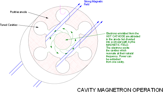
The magnetron is essentially a diode valve with a cylindrical anode. The anode has cavities dimensioned to resonate at the required microwave frequency; they behave like tuned circuits. A strong magnetic field is arranged to pass through the valve. Electrons emitted from the cathode would, in the normal way be attracted directly to the anode. However, the magnetic field causes them to take a circular path. As the stream of electrons pass the cavities they resonate and the electrons are bunched as in the klystron. Strong oscillations build up in the cavities and can be extracted as microwave energy. It is a self oscillating device. As the power is applied to it oscillation will commence and build up in amplitude and the frequency will vary somewhat. As a result it is not suitable for many sophisticated radar systems which require close frequency control and well controlled pulse shapes. Nevertheless modern versions are still widely used and can provide pulsed outputs of several megawatts at the lower microwave frequencies ( say 2 to 5 Ghz. i.e. 2,000 to 5,000 Mhz) albeit at a duty cycle of about 0.1%. This means that the interval between pulses must be about 1,000 times the length of the pulse. The average power is thus only a few kilowatts. Extremely high voltages and currents are involved: as much as 75 kV at currents of 100 Amps. This must be applied in short pulses to produce the required pulsed RF output. It is this which makes the design of Radar transmitters so different.
More sophisticated Radars use klystrons as amplifiers in a similar way to TV transmitters.
However, the design of the klystron is somewhat different as a result of the requirement
for short pulses of very high power. Pulse powers of several megawatts are achieved
but the thermal design need only be based on the much lower average power. Very high
voltages, sometimes in excess of 100kV are applied. Voltages such as this can produce
dangerous levels of x-
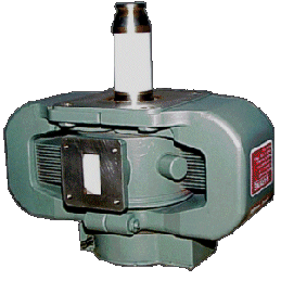
This picture shows a medium power magnetron (about 5kW). The large yoke around it is the magnet. The rectangular port at the front is the connection for the output waveguide. Microwave signals, especially high power signals are normally carried in waveguides rather than cables.
The long insulator is necessary for application of the high voltage supply. This is normally a negative voltage applied to the cathode. The anode, which carries no signal, is grounded which makes cooling easier than in a conventional valve.